Products and Services


Nuclear facilities require area, process, and effluent radiation monitoring systems (RMS) that continuously measure radiation to ensure safety and satisfy regulatory requirements. APANTEC, LLC has designed, built, and installed a wide range of RMS for nuclear power plants, accelerators, U.S. national laboratories, government agencies, PET centers, and the U.S. military. The following summarizes APANTEC complete RMS, standard components designed and manufactured by APANTEC for use in APANTEC complete RMS, APANTEC software solutions, and APANTEC services. For more details about any of these capabilities, contact the APANTEC, LLC sales department.
APANTEC RMS are integrated systems that allow real-time, remote and local radiation monitoring in a wide range of environments. APANTEC RMS integrate APANTEC designed detectors and associated preamplifiers and signal channel analyzers, gas/liquid samplers, assemblies, and software to form complete systems. Apantec provides the following complete RMS. Custom designs are also available. Please contact us if you don’t see exactly what is needed.
APANTEC, LLC has designed several standard instruments, which are combined and configured to form complete RMS that satisfy site specific needs. This approach provides a great deal of flexibility to meet site specific customer requirements. All systems are fully documented and tested to meet site-specific specifications and for long term support. APANTEC, LLC standard instruments include:
It is often desirable to integrate the radiation monitoring channels into a single software database for central display and control, as well as data archiving and retention. This is achieved using software developed at APANTEC, LLC.
APANTEC offers a full service preventive maintenance and repair program to support any & all Nuclear Generating Stations which are currently using both Nuclear Research Corporations and Canberra supplied detectors, preamplifiers as well as remote and local alarm indicators:
For more details about any of these capabilities, contact the APANTEC, LLC sales department.
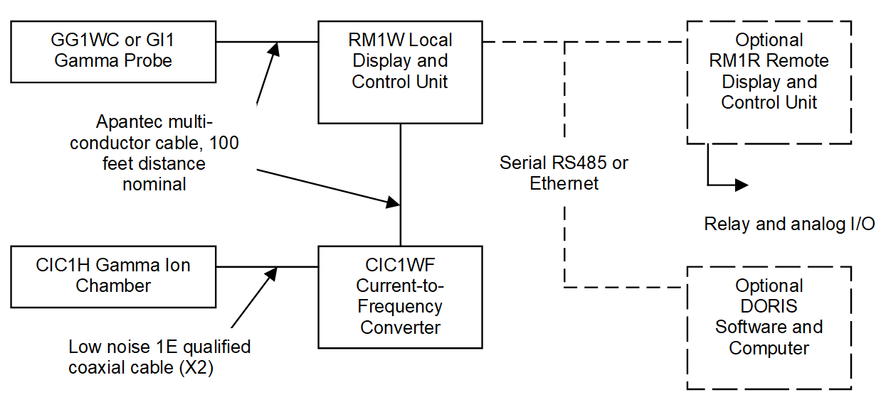
Area RMS are designed to continuously monitor ambient gamma and neutron activity levels using GG1W Gamma GM Detectors , GI1 Ion Chamber Detectors , CIC1H Gamma Ion Chamber Detectors , SD Series Scintillation Detectors, and NB1X/NH1X Neutron Detectors depending on the gamma or neutron field conditions and detector locations. Each channel typically includes a locally mounted detector and a display and control unit. The local display and control unit also provides local annunciation of an alarm condition to warn site personnel of channel malfunctions or abnormal activity levels. Optionally, a remote display and control unit can also be provided for remote operation of the monitoring channel. The remote display and control unit can be replaced by the DORIS software and computer for remote operation of multiple radiation monitoring channels. A Power Over Ethernet option is available to integrate the system using standard, off-the-shelf components. A block diagram of a typical area radiation monitoring channel is shown below.
| GG1WC based channel: | 10 μR/h to 10,000 R/h |
| GI1 based channel: | 100 μR/h to 100 R/h |
| CIC1H based channel: | 2.5E-01 to 5E+07 R/hr |
| SD Series based channel: | 1E+0 to 1E+7 CPM (wide range optional) |
| NB1X based channel: | 2 μSv/h to 10 mSv/h |
| NH1X based channel: | 10 nSv/h to 100 mSv/h |
Apantec offers an extensive line of continuous air monitors through the
| Single channel, measures either radioactive combined particulate/iodine OR noble gas activity | |
| Dual channel, measures either radioactive particulate and iodine separately OR combined particulate/iodine and noble gas activity | |
| Three channel, measures radioactive particulate, iodine, and noble gas activity separately |
The AM series may utilize the AS43F Fixed Filter Particulate or Iodine Sampler , the AS34M Moving Filter Particulate or Iodine Sampler , and/or the GS45 Noble Gas Sampler of standard instruments designed.
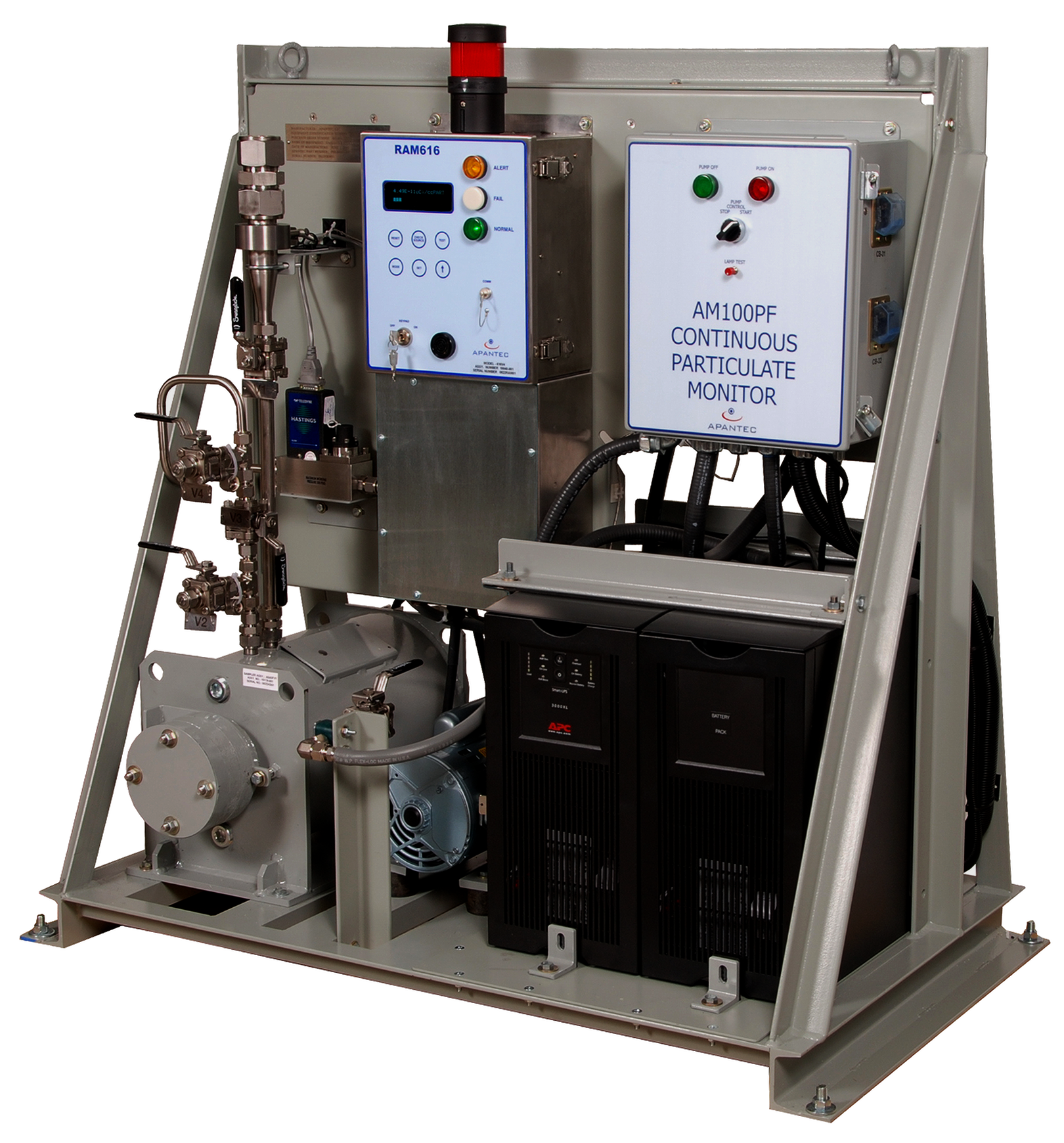
The AM1F is a low profile fixed filter monitor designed to continuously collect and measure the quantity of radioactive beta particulates or gamma iodines in the sample stream. The system will monitor radioactive airborne levels in either working spaces, or via a process tubing connection to a remote stack, duct or other air space. The AM1F can be set for representative sampling if desired.
The sampler uses a fixed filter geometry with three inches of lead shielding. Internal to the sampler is an APANTEC SD201P beta scintillation detector for sensitivity to beta particles or SD220N gamma scintillation detector for measurement of iodines. The sampler accepts both a particulate filter paper and an optional activated charcoal cartridge using a common filter holder mechanism. The detector is positioned in a lead shield, Model AS43F in close proximity to the sample deposition point.
The detector has an associated Preamp/SCA model SDA3E for operation of the detector, and for pulse analysis. The output of the SDA3E is wired to a locally mounted RM1W Display and Control Unit. The SDA3E Preamplifier includes three separate single channel analyzer circuits which are set to window the beta, activities. A vacuum pumping system capable of 1 SCFM (30 LPM) is included on the AM1F monitoring skid. The pumping system will include local mass flow control of the process fluid to maintain sampling rates during filter loading. Pump controls will be provided on the local skid. The local RM1W units interface with an optional remote RM1R unit or DORIS software via serial communications for full remote control of each channel. When used for isokinetic sampling, the flow rate on the sample skid is controlled using a velocity signal from the sample point to minimize sample loss during transmission of the sample to the filter deposition point.
Back to "Process and Effluent RMS"
The model AM1G is a single channel air monitoring system used for continuous measurement of noble gases. The AM1G includes an APANTEC model GS45 Noble Gas Sampler for repeatable measurement and attenuation of gamma background energies. The GS45 provides a sensitive volume of approximately five liters surrounded by a 4" thick lead shield. A particulate and iodine inline fixed filter is provided upstream of the inlet to the GS45 noble gas volume to remove unwanted particulate and iodine activity from interfering with the noble gas measurement. Internal to the sampler and mounted in close proximity to the filter media is an APANTEC SD series scintillation detector. The preferred detector is the APANTEC model SD201PB beta/gamma scintillation detector.
The SD201PB detector has an associated Preamp/SCA model SDA3E for operation of the detector, and for signal conditioning. The output of the SDA3E is wired to a locally mounted RM1W display and control unit. The detector includes a beta sensitive plastic scintillator for measurement of beta activity. A vacuum pumping system capable of 1 SCFM (30 LPM) is included on the AM1G monitoring skid. The pumping system includes a flow control valve and rotameter for establishing the desired flow rate through the sampler. Pump controls will be provided on the local skid. The local RM1W units interface with remote RM1W units via serial communications for optional full remote control of each channel.
| Lower Limit of Detection: | 1E-7 μCi/cc |
| Dynamic Range: | 1E-7 to 1E-1 μCi/cc (Referenced to Xe-133) |
Back to "Process and Effluent RMS"
The AM2IGM is a continuous air monitoring system designed to measure the iodine and noble gas activity in a sample air stream. The AM2IGM uses two separate measuring channels arranged in series to perform the measurement. A common vacuum pumping system is used for transport of the sample gases through the system. Local RM1R display and control units are included for system operation, data concentration and communication. The iodine channel uses an AS3M lead shielded moving filter sampler providing collection of airborne particulate and iodine on industry standard charcoal impregnated filter paper in a roll form.
The iodine channel will be equipped with a gamma sensitive scintillation detector (model SD220N) for detection of gamma emitting iodines. The SDA3E unit communicates with the skid-mounted display and control unit (model RM1R) using Ethernet (TCP/IP), RS232 or RS485 communications for display of the measured activity and for alarm determination. The exhaust from the iodine channel is plumbed to the inlet of the noble gas monitoring channel. The sample gases, with particulate and iodine activity removed, enter the noble gas sampler for measurement. The noble gas sampler (model GS45) is a lead shielded sampler enclosing a sensitive volume.
A SD201PB beta scintillation detector is located with the sensitive volume for measurement of noble gas activity. The detector detects the nuclear pulses, provides biasing voltage, and transmits the count rate information to the locally mounted SDA3E analyzer.
The noble gas sampler includes a vacuum transducer to automatically correct the measured activity to standard pressure. The Vacuum pumping system uses a positive displacement carbon vane pump for transport of sample gases through the monitoring system. A mass flow meter and proportional control valve allows the sample flow rate to be either manual set to the desired flow or to match the sample flow rate to a stack or vent velocity for representative sampling. The flow rate is provided to the local RM1R electronics for determination of total release and for calculation of concentrations. Alarms are included for annunciation of a low flow condition.
| Lower Limit of Detection: | 1E-11 μCi/cc |
| Dynamic Range: | 1E-11 μCi/cc to 1E-5 μCi/cc (Referenced to I-131) |
| Lower Limit of Detection: | 1E-7 μCi/cc |
| Dynamic Range: | 1E-7 μCi/cc to 1E-1 μCi/cc (Referenced to Xe-133) |
Back to "Process and Effluent RMS"
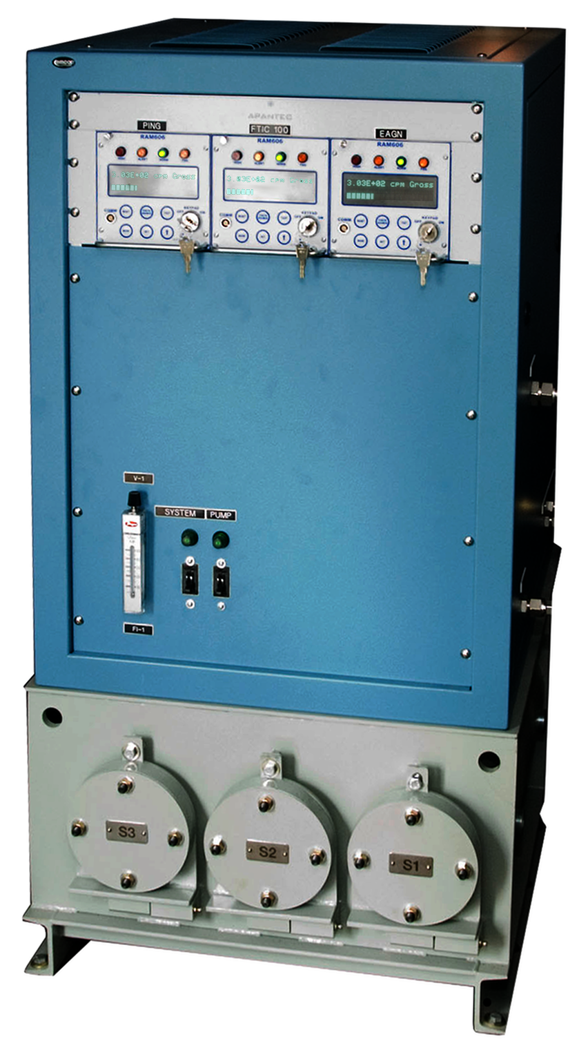
The AM31F is a continuous air monitoring system designed to measure the particulate, iodine and noble gas activity in a sample airstream. The AM31F uses three separate measuring channels arranged in series within the same lead shield to perform the measurement. A common vacuum pumping system is used for transport of the sample gases through the system. Local RM1R display and control units are included for system operation, data concentration and communication.
The particulate channel uses a lead shielded fixed filter sampler providing collection of airborne on industry standard 47mm diameter filter paper. The filter paper deposition is designed to provide an even distribution and positions the active end of the detector in close proximity to the filter media for maximum sensitivity. The particulate channel will be equipped with a beta sensitive plastic scintillation detector (model SD201P) for detection of beta emitting particles. The detector interfaces with a locally mounted spectrum analyzer (model SDA3E) which provides the low voltage power to the detector, interfaces the detector/SCA with the ratemeter, and provides an automatic gain control function.
The SDA3E unit communicates with the skidmounted display and control unit (model RM1R) using Ethernet (TCP/IP), RS232 or RS485 communications for display of the measured activity and for alarm determination. The exhaust from the particulate channel is plumbed to the inlet of the iodine monitoring channel. The iodine monitoring channel is similar to the particulate channel and also uses a lead shielded sampler for collection of the iodine activity. In the iodine channel, a TEDA activated charcoal cartridge or silver zeolite cartridge replaces the particulate fixed filter media. A gamma sensitive scintillation detector (model SD220N) is placed within the lead shielded sampler with the sensitive end exposed to the collection cartridge. The SD220N detects the gamma events and provides the spectral information to an external SDA3E analyzer unit. The sample gases, with particulate and iodine activity removed, enter the noble gas sampler for measurement. The noble gas sampler is a lead shielded sampler enclosing a sensitive volume. A SD220N gamma scintillation detector or SD201P beta scintillation detector is located with the sensitive volume for measurement of noble gas activity.
The detector detects the nuclear pulses, provides biasing voltage, and transmits the count rate information to the locally mounted SDA3E analyzer. The noble gas sampler includes a vacuum transducer to automatically correct the measured activity to standard pressure. The Vacuum pumping system uses a positive displacement carbon vane pump for transport of sample gases through the monitoring system. A flow meter and proportional control valve allows the sample flow rate to be manually set to the desired flow.
The AM31F is available in three configurations depending on the desired measurements(s):| One Channel | |
| Two Channel | |
| Three Channel |
| Lower Limit of Detection: | 1E-11 μCi/cc |
| Dynamic Range: | 1E-11 μCi/cc to 1E-5 μCi/cc (Referenced to Cs-137) |
| Lower Limit of Detection: | 1E-7 μCi/cc |
| Dynamic Range: | 1E-7 μCi/cc to 1E-1 μCi/cc (Referenced to Xe-133) |
Back to "Process and Effluent RMS"
The AM3PIGF is a continuous air monitoring system designed to measure the particulate, iodine and noble gas activity in a sample airstream. The AM3PIGF uses three separate measuring channels arranged in series to perform the measurement. A common vacuum pumping system is used for transport of the sample gases through the system. Local RM1R display and control units are included for system operation, data concentration and communication. The particulate channel uses a lead shielded fixed filter sampler providing collection of airborne on industry standard 47mm diameter filter paper. The filter paper deposition is designed to provide an even distribution and positions the active end of the detector in close proximity to the filter media for maximum sensitivity.
The particulate channel will be equipped with a beta sensitive plastic scintillation detector (model SD201PB) for detection of beta emitting particles. The detector interfaces with a locally mounted pulse analyzer (model SDA3E) which provides the low voltage power to the detector, interfaces the detector with the ratemeter, provides three independent user adjustable single channel analyzer circuits, and provides an automatic gain control function.
The SDA3E unit communicates with the skid-mounted display and control unit (model RM1R) using Ethernet (TCP/IP), RS232 or RS485 communications for display of the measured activity and for alarm determination. The exhaust from the particulate channel is plumbed to the inlet of the iodine monitoring channel. The iodine monitoring channel is similar and also uses a lead shielded sampler for collection of the iodine activity. In the iodine channel, a TEDA activated charcoal cartridge or silver zeolite cartridge replaces the particulate fixed filter media. A gamma sensitive scintillation detector (model SD115N) is placed within the lead shielded sampler with the sensitive end exposed to the collection cartridge. The SD115N detects the gamma events and provides the pulse information to an external SDA3E analyzer unit. The sample gases, with particulate and iodine activity removed, enter the noble gas sampler for measurement. The noble gas sampler (model GS45) is a lead shielded sampler enclosing a sensitive volume.
A SD201PB beta/gamma scintillation detector is located with the sensitive volume for measurement of noble gas activity. The detector detects the nuclear pulses, provides biasing voltage, and transmits the count rate information to the locally mounted SDA3E analyzer. The noble gas sampler includes a vacuum transducer to automatically correct the measured activity to standard pressure. The Vacuum pumping system uses a positive displacement carbon vane pump for transport of sample gases through the monitoring system. A mass flow meter and proportional control valve allows the sample flow rate to be either manual set to the desired flow or to match the sample flow rate to a stack or vent velocity for representative sampling. The flow rate is provided to the local RM1R electronics for determination of total release and for calculation of concentrations. Alarms are included for annunciation of a low flow condition.
| Lower Limit of Detection: | 1E-11 μCi/cc |
| Dynamic Range: | 1E-11 μCi/cc to 1E-5 μCi/cc (Referenced to Cs-137) |
| Lower Limit of Detection: | 1E-11 μCi/cc |
| Dynamic Range: | 1E-11 μCi/cc to 1E-5 μCi/cc (Referenced to I-131) |
| Lower Limit of Detection: | 1E-7 μCi/cc |
| Dynamic Range: | 1E-7 μCi/cc to 1E-1 μCi/cc (Referenced to Xe-133) |
Back to Process and Effluent RMS
The AM3GFA Accident Range Noble Gas Monitor is designed to measure high range noble gas activity on a continuous basis. Included with the AM3GFA are parallel particulate/iodine collectors for retention of high activity levels of particulates and iodine. The P/I filters are lead shielded to reduce ALARA concerns and include active gamma monitoring of the accumulated dose. A gamma GM detector (model GGW1) is associated with each P/I filter to measure the accumulated dose rate on the filter media. Once the sample gases have passed through the parallel collectors, the noble gas activity level is measured in a lead shielded sample volume. The GGW1 detector is located within the lead shield and inserted into the sensitive volume for measurement. The output from the detector communicates with the skid mounted display and control unit (model RM1R) using Ethernet (TCP/IP), RS232, or RS485 communications for display of the measured activity and for alarm determination.
The noble gas sampler includes a vacuum transducer to automatically correct the measured activity to standard pressure. Local RM1R display and control units are included for system operation, data concentration and communication. The vacuum pumping system uses a positive displacement metal bellows pump for transport of sample gases through the monitoring system. A mass flow meter and proportional control valve allows the sample flow rate to be either manually set to the desired flow or to match the sample flow rate to a stack or vent velocity for representative sampling. A flow rate signal is provided to the local RM1R electronics for determination of total release and for calculation of concentrations. Alarms are included for annunciation of a low flow condition. The AM3GFA operates in conjunction with the APANTEC model(s) AM3PIGM or AM3PIGF normal range skid to provide seamless monitoring over the entire range. Upon increasing activity measured by the AM3PIGM/F normal range monitor, the accident range AM3GFA monitor will automatically start the sample pump and begin monitoring. Once the activity level drops, the AM3PIGM/F will automatically begin normal range monitoring and the AM3GFA accident level monitor will stop monitoring activities. The AM3GFA samples at a significantly lower sample flow rate to reduce the build up of high radioactivity on the particulate and iodine filters.
Back to Process and Effluent RMS
The PIM403 is a process or effluent monitor designed to continuously measure the quantity of radioactive gamma isotopes in the sample stream. The system is designed to monitor gamma levels in an inline arrangement and includes a flange-to-flange sampler for process connection.
The PIM403 monitor uses a sampler design with four inches of lead shielding in a 3Pi geometry. The sampler is provided with 150 pound rated raised face flanges to allow it to be mounted to an existing pipe containing the fluid to be measured. Internal to the sampler and accessed via a maintenance port is an APANTEC SD220N scintillation detector for sensitivity to gamma emitting isotopes in the process pipe. The detector is located within a stainless steel drywell to provide a repeatable geometry. The detector has an associated model SDA3E Preamp/SCA for operation of the detector, and for pulse analysis. The output of the SDA3E is wired to a locally mounted RM1W display and control unit. The RM1W provides for complete local display and control of the monitoring channel, as well as providing local indication of alarm trips and system malfunctions. The RM1W includes serial communications ports for operation and display of the monitoring system from a remote location. Mounted to the exterior of the sample shield is an optional model CS-9G isotopic check source for routine operability checks. The maintenance cycle for the PIM403 Monitor is 24 months. The extended maintenance cycle is achievable because there are no moving parts, uses all low current consuming electronics, and takes advantage of the APANTEC exclusive gain stabilization circuit that automatically compensates gain shifts caused by changes in temperature and aging. APANTEC offers full qualification to the latest nuclear codes and standards including Class 1E Safety Applications. Qualifications are performed to the guidelines of IEEE-323, IEEE-344 and Regulatory Guide 1.97.
Back to Process and Effluent RMS
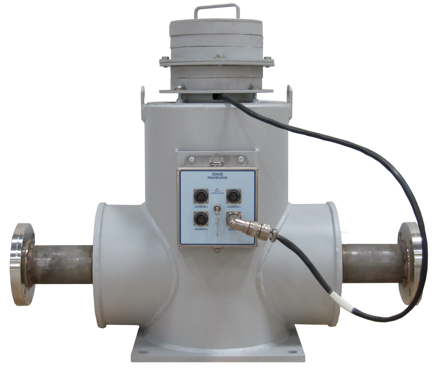
The POM403 is a process or effluent monitor designed to continuously measure the quantity of radioactive gamma isotopes in the sample stream. The system is designed to monitor gamma levels in an adjacent-to-line arrangement and includes a clamp-on style sampler for process connection The POM-403 monitor uses a split shield design with four inches of lead shielding in a 3Pi geometry. Internal to the sampler and accessed via a maintenance port is an APANTEC SD220N scintillation detector for sensitivity to gamma emitting isotopes in the process pipe. The detector is located within a stainless steel drywell to provide a repeatable geometry for measurement. The detector has an associated model SDA3E Preamp/SCA for operation of the detector, and for pulse analysis. The output of the SDA3E is wired to a locally mounted RM1W display and control unit. The RM1W provides for complete local display and control of the monitoring channel, as well as providing local indication of alarm trips and system malfunctions. The RM1W includes serial communications ports for operation and display of the monitoring system from a remote location. Mounted to the exterior of the sample shield is an optional model CS-9G isotopic check source for routine operability checks. The maintenance cycle for the POM403 Monitor is 24 months. The extended maintenance cycle is achievable because there are no moving parts, uses all low current consuming electronics, and takes advantage of the APANTEC exclusive gain stabilization circuit that automatically compensates gain shifts caused by changes in temperature and aging.
APANTEC offers full qualification to the latest nuclear codes and standards including Class 1E Safety Applications. Qualifications are performed to the guidelines of IEEE-323, IEEE-344 and Regulatory Guide 1.97.
Back to Process and Effluent RMS
The APANTEC VDM1 Vent/Duct Monitoring System is designed for direct mounting into the vent or duct to be monitored. Each VDM1 includes a detector mount for insertion of the detector into the vent or duct, a model SD201PB beta/gamma scintillation detector, SDA3E signal analyzer unit, and locally mounted RM1W display and control unit. The detector is positioned using the detector mounting bracket with the sensitive end within the vent or duct to permit measurement of the beta particles. The SD201PB beta/gamma detector measures both the beta noble gas activity and the gamma background level. The gamma background level is then subtracted from the net detector reading to provide a true measurement of beta noble gases present in the duct or vent. Operability checks are performed by pulsing the internal LED within the detector enclosure to produce an upscale indication.
| Lower Limit of Detection: | 1E-7 μCi/cc (Referenced to Xe-133) |
Back to Process and Effluent RMS
The MSL is a dual purpose gamma radiation monitoring system allowing simultaneous measurement of both noble gases in the steam line and primary and secondary leak rate of N-16 in the steam generator. The system is designed to monitor gamma levels in an adjacent-to-line arrangement and includes a clamp-on style shield. The shield design with four inches of lead shielding in a 3Pi geometry can be mounted on the floor adjacent to the steam line, or mounted with the lead shield clamped to the steam line.
Internal to the shield and accessed via a maintenance port is an Apantec SD220B scintillation detector for sensitivity to gamma emitting isotopes in the steam pipe. The detector is located within a stainless steel drywell to provide a repeatable geometry for measurement. The SD220B uses a 2" x 2" BGO crystal for increased sensitivity to high energy N-16 present in the steam line. The detector is designed for high temperature operation to provide reliable operation at the extended temperatures present in an adjacent to steam line environment.
The detector has an associated model SDA3E dual channel Preamp/SCA for operation of the detector, and for pulse analysis. The output of the SDA3E is wired to a locally mounted RM1W Display and Control Unit. The SDA3E provides the ability to establish separate regions of interest to allow simultaneous measurement of both noble gases and N-16 in the steam line. The detector is also temperature stabilized for high temperature operation.
The RM1W provides for complete local and remote display and control of the monitoring channel, as well as providing indication of alarm trips and system malfunctions. The RM1W includes serial & Ethernet communications ports for centralized computer based control and display of the monitoring system. Mounted to the exterior of the sample shield is an optional model CS-9G isotopic check source for routine operability checks.
Apantec offers full qualification to the latest nuclear codes and standards including Class 1E Safety Applications. Qualifications are performed to the guidelines of IEEE-323, IEEE-344 and Regulatory Guide 1.97.
Back to Process and Effluent RMS
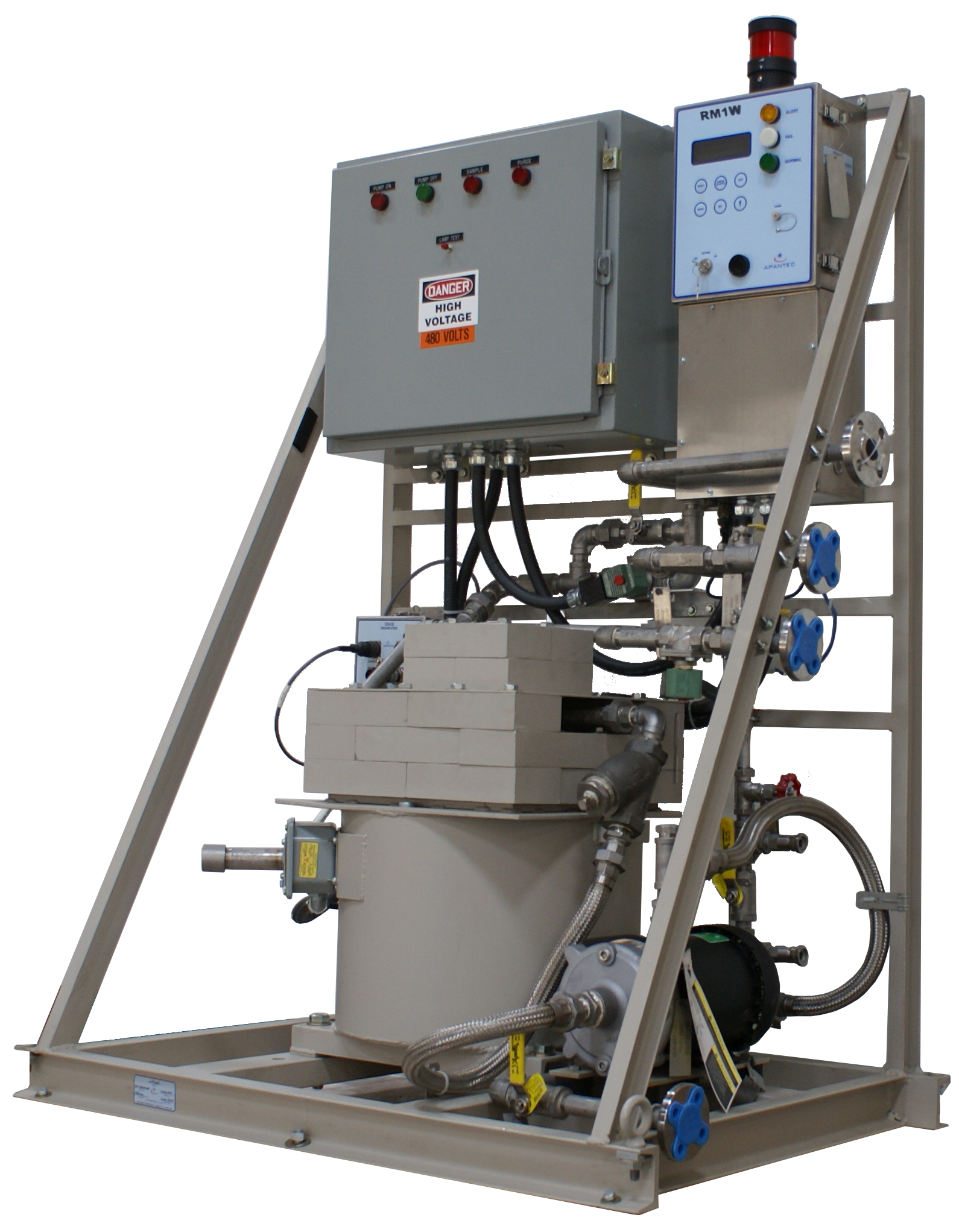
The LM1 monitoring system consists of a SD220N gamma scintillation detector with SDA3E preamplifier/SCA unit, local RM1W display and control unit, LS44 liquid sampler, liquid pumping system, and local cables to interconnect the system electronics. The detector will continuously measure the gamma energies from the liquid sample stream and provide nuclear pulses to the preamp/SCA. The preamplifier/SCA unit can be set to operate in differentiate mode measuring a desired region of interest, or it can be operated in integrate mode measuring gross gamma activity.
The detector/preamplifier electronics also includes a three user adjustable single-channel analyzer circuits for determination of the desired regions of interest. The LM1 liquid monitoring system will achieve a lower limit of detection of 2.7E-8 uCi/cc of Cs-137 in a 10 μR/hr Cs-137 gamma background with ten minutes integration time and two standard deviations of background.
Back to Process and Effluent RMS
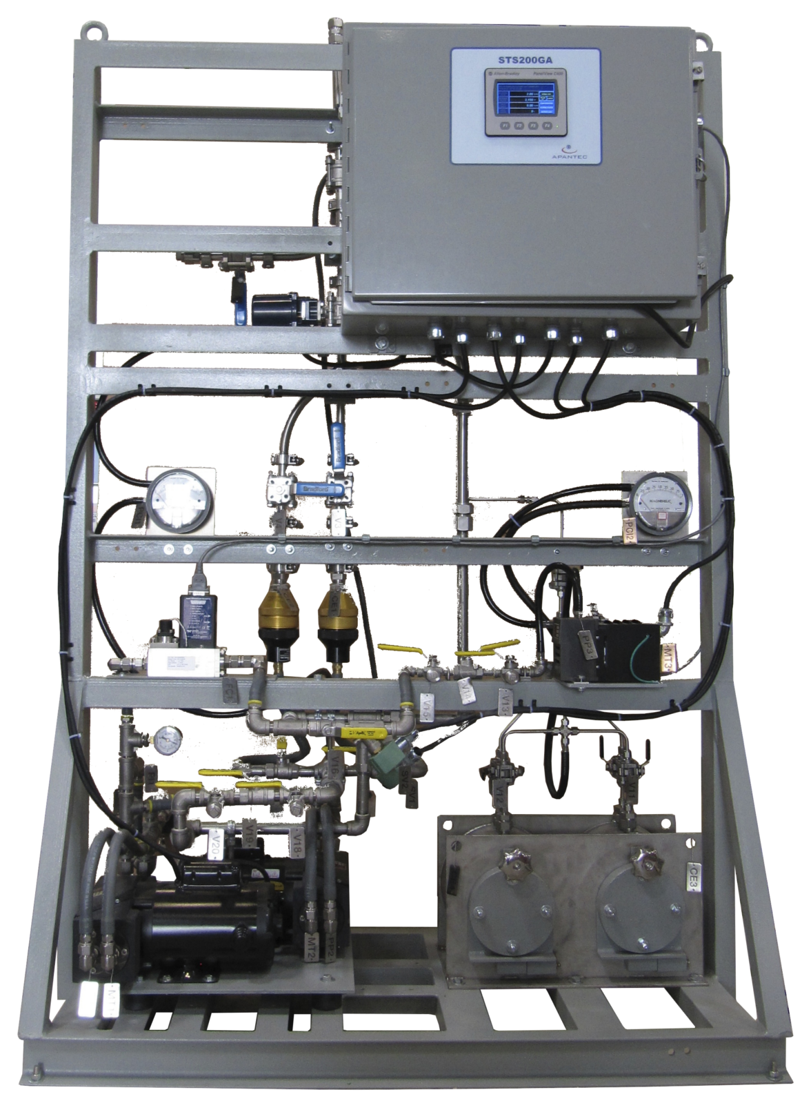
The STS200GA Stack Sampling System is designed to sample particulate, iodine and noble gas contained in the ventilation exhaust or stack effluent. The STS200GA system withdraws a measured sample from the stack and then transports the sample through low loss components to high efficiency air filters. The mass flow rate and sample mass flow rate are accurately tracked and recorded to allow direct correlation of activity concentration collected on the filter paper to the stack effluent activity concentration. Parallel flow paths are provided for normal range P/I filters with redundant vacuum pumps for motive force. A splitter block designed per ANSI N13.1-1969 diverts the normal sample flow to the parallel filter elements. A skid mounted PLC Controller monitors the stack flow rate and temperature, and sample flow rate and temperature, and controls system and component Fail relays and other communications to notify plant personnel of system status.
Upon notification of an accident condition, the system automatically switches to accident range sampling. The system can also be operated continuously via selection of front panel controls for manual sampling. A separate flow splitter block diverts a portion of the sample gases to the accident level filters and a separate vacuum pump provides motive force through the accident level filters. The normal range sample pump continues to withdraw a representative sample at the normal sample flow rate (56.6 SLPM) to maintain sampling per ANSI N13.1-1969. The accident range sample pump uses a reduced sample flow rate of 1 SLPM to minimize contamination expected from high levels of particulates and iodines and allow collection for a longer time interval between filter exchange.
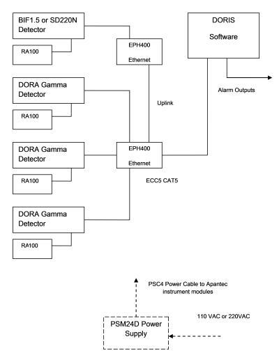
Positron Emission Tomography (PET) centers require monitoring systems to continuously measure the levels of ambient gamma radiation and airborne radioactive particles. Selected PET center applications may also require monitoring of ambient neutron activity. It is often desirable to integrate the radiation monitoring channels into a single software database for central display and control, as well as data archiving and retention.
Apantec, LLC has designed several standard instruments to meet these monitoring requirements. The design approach focuses on standard modules that are interconnected and configured to meet site specific needs. Each Apantec instrument is provided with an Ethernet port for ease of installation and flexibility. Standard CAT5 communications cable is used for interconnection of the Apantec, LLC devices.
Display and control of the radiation monitoring channels can be accomplished using either discreet microprocessor based display and control units or using a central database software program. Each Apantec instrument module includes an Ethernet interface, allowing each device to be interconnected using readily available CAT5 communications cable. Each method of display and control is described in the following paragraphs. Display units include:
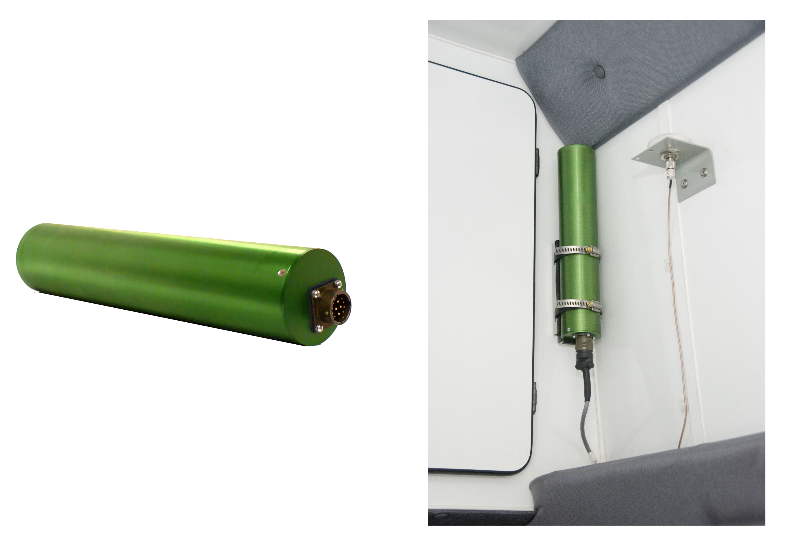
The GG1W Intelligent Gamma Probe is an integrated real-time Gamma radiation-monitoring device that provides highly accurate indication of ambient Gamma radiation over a wide range. The GG1W uses a halogen quenched Geiger Müeller tube for sensitivity to ambient gamma radiation levels. The GM tube is operated using a "Time-To-Count" method which removes the limitations associated with traditional "constant bias" GM tube circuits. The GG1W will detect gamma radiation from 80 keV to 2 MeV with a linearity of ±20%. The detector provides a dynamic range of 10-4 mSv/h to 105 mSv/hr. The GG1W is electrically connected via a multi-conductor shielded cable to an associated APANTEC Display and Control unit.
The GG1W is housed in a rugged, cylindrical aluminum housing with a NEMA4 rating. Apantec offers Models GG1W (wide range), GG1WC (Check Source version), and GG1WL (Low range version with one GM tube). All of these types can also have the Sieverts version SI Units of measurement (Sv/hr(H*10)).
| Detector Type: | Geiger Müeller tube |
| Range: | GG1W, GG1WC: 1E-4 mSv/h to 1E+5 mSv/hr (10 μR/hr to 10,000 R/hr) GG1WL: 1E-4 mSv/h to 100 mSv/hr (10 μR/hr to 10 R/hr) |
| Energy Range: | 80 keV to 2 MeV |
| Energy Response: | ±20% from 80 keV to 2 MeV, Reference 137Cs |
| Saturation: | Won"t saturate in fields up to 10,000 R/hr |
| Accuracy: | ±15% over entire range |
| Linearity: | ±5% |
| Response Time: | 4 s |
| Operating Temperature: | -31 to 140 °F (-35 to 60 °C) |
| Operating Humidity: | 0-95% RH |
| Operating Voltage: | 12 VDC supplied by RM unit |
| Dimensions: | 7 in. L x 2.5 in. dia. |
| Weight: | 0.9 kg (2 lbs.) nominal, not including detector mount |
| Check Source: | internal 90Sr, 9 μCi, remotely operated, spring return (GGW1C only) |
The GG2W Intelligent Gamma Probe is an integrated real-time Gamma radiation monitoring device that provides highly accurate indication of ambient Gamma radiation over a wide range. The GG2W uses a pair of halogen quenched Geiger Müeller tubes for sensitivity to ambient gamma radiation levels. The GM tubes are operated using a “Time-To-Count” method which removes the limitations associated with traditional ‘constant bias’ GM tube circuits.
The GG2W will detect gamma radiation from 50 keV to 3 MeV with a linearity of ± 5%. The detector provides a dynamic range of 1 μR/hr to 1,000 R/hr. The GG2W is electrically connected via a multi-conductor shielded cable to an associated Apantec’s Display and Control unit. The GG2W is housed in a rugged cylindrical aluminum housing with a NEMA 4 rating and is also available with SI Units of measurement Sv/hr (H*10)
| Detector Type: | Geiger Müeller tube |
| Range: | 1 μR/hr to 1,000 R/hr |
| Energy Range: | 50 keV to 3 MeV |
| Energy Response: | ±20% 80 keV to 1.5 MeV (Reference Cs-137) |
| Saturation: | Will not saturate in fields up to 100,000 R/hr |
| Accuracy: | ±15% over entire range |
| Linearity: | ±5% |
| Response Time: | 4 s |
| Environment: | -31°F to 140°F (-35°C to +60°C), 0-95% RH |
| Operating Voltage: | 12 VDC |
| Dimensions: | 12”L x 2.5” diameter |
| Weight: | 2 lb (1 kg) nominal, not including detector mount |
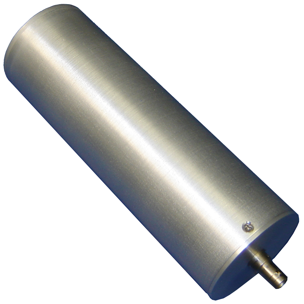
The GI1 Ion Chamber detector is a sealed ion chamber probe packaged in a cylindrical aluminum enclosure and fitted with a multi-pin circular connector for interconnection to an APANTEC RM1 series display unit. The GI1 is used on area monitoring applications with transient or burst radiation levels, or those channels with anticipated high activity such as containment / post accident detection.
The GI1 includes a current-to-frequency converter for converting the current output signal from the ion chamber sensor into pulses suitable for counting by the RM1 series display unit input circuitry. The RM1 display and control unit provides Ethernet and serial RS485 communications for networking to a central computer using the APANTEC DORIS software.
The GI1 measures a range of 100 μR/hr to 100 R/hr. The GI1 is also available with an internal isotopic check source. These instruments are designated as the models GI1C. For high range and high TID applications, please refer to the APANTEC model CIC1 Ion Chamber detector design.
| Detector Type: | Ion chamber, sealed |
| Range: | 100 μR/hr to 100 R/hr |
| Energy Response | ±20% from 80 keV to 2.5 MeV (Referenced to Cs-137) |
| Saturation | Will not saturate in fields up to 1,000 R/hr |
| Accuracy: | ±20% over entire range |
| Operating Temperature | 14°F to 122°F (-10°C to 50°C) |
| Operating Humidity: | 0-95% RH |
| Operating Voltage | 12 VDC, biasing voltages internally generated |
| Dimensions | 12.5 in. (317.5 mm) L x 2.5 in. (63.5 mm) dia. |
| Weight: | 3 lb (1.35 kg) nominal |
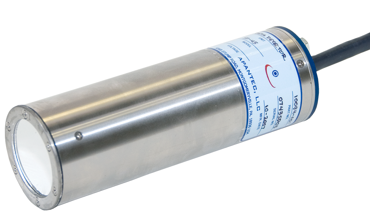
The Apantec SD series detectors are scintillation based radiological detectors primarily used for process and environmental radiation monitoring systems in nuclear power plants. A separate single channel analyzer (SCA) model SDA3E is used for pulse height analysis and biasing voltages. The detectors include a gain stabilization circuit for drift free operation. The SD series detectors include a scintillator, photomultiplier tube, mu-metal shield, and dynode chain in a cylindrical enclosure. A light emitting diode (LED) is located in the detector enclosure for automatic gain control. A temperature sensor also located within the detector provides a temperature signal for temperature compensation. The scintillation material is selected based on the process conditions and required sensitivity.
A separate spectrum/analyzer enclosure (Model SDA3E) is located in proximity to the detector and is used to perform several functions. A closed-loop feedback control circuit in the analyzer provides automatic gain stabilization of the scintillation detector and corrects for variations in gain due to temperature, aging, and power supply drift. The spectrum/analyzer enclosure includes controls for the SCA circuits and can be set to integrate up to three specific regions of interest when used for gamma applications, or set to operate in gross counting mode. Software algorithms are included to provide user adjustable filter time to integrate the count rate data from each ROI. The spectrum/analyzer enclosure is provided with a NEMA4 rating and is designed for mounting to a flat surface. The detector is interconnected to the SDA/analyzer enclosure using a one meter (nominal) cable. Serial communication is used for interconnection between the SDA3E and a remote display and control unit. The interconnection cables are provided fully assembled and tested. All SD series detectors are provided fully calibrated to NIST standards. Gain Stabilization Benefits: The SD/SDA-series operates with a unique gain stabilization circuitry for temperature compensated drift-free operation (< 5% per year), resulting in improved accuracy and an extended 18 month calibration cycle. Inside the detector is a light emitting diode (LED) that is optically coupled to the light pipe assembly. The LED is pulsed at a known low pulse repetition rate with a known pulse width and amplitude to provide a reference signal. The SDA3E contains circuitry that compares the LED pulses with a reference to provide closed loop feedback for automatic gain compensation, thus offsetting the effects of thermal drift and aging. A thermally compensated LED, "gain stabilization" provides distinct advantages over designs based upon the use of radioactive seeds. Radioactive seed type of scintillation detectors have more expensive crystals and must deal with disposal issues when the crystal is no longer usable. In addition, isotopes gain shift differently and are not uniform from isotope to isotope, thereby causing inaccuracies of measurement. Also, the statistical nature of the reference signal from the radioactive seed does not allow use of low count rates.
Apantec has developed the SD series of scintillation detectors for use in process monitoring systems. The SD series detectors include a scintillator, photomultiplier tube, mu-metal shield, dynode chain, and Lucite light pipe in a cylindrical enclosure. A light emitting diode (LED) is located in the Lucite light pipe for automatic gain control. A temperature sensor located within the Lucite light pipe provides a temperature signal for temperature compensation. The detector housing is 2.5" in diameter x 7 inches long. The scintillation material is selected based on the type(s) of radiation to be measured.
A separate preamplifier/analyzer enclosure located in proximity to the detector is used to perform several functions. The preamplifier provides operating voltage to the associated scintillation detector for detector operation. A closed loop feedback control circuit in the preamplifier/analyzer provides automatic gain stabilization of the scintillation detector, correcting for variations in gain due to temperature, aging and power supply drift. Finally, the preamplifier/analyzer enclosure includes a SCA circuit which can be set to integrate up to three specific regions of interest when used for gamma applications, or set to operate in gross counting mode.
An optional MCA with full 1024 channel gamma spectrum can also be provided for more detailed analysis. The preamplifier/analyzer enclosure is provided with a NEMA4 rating and is designed for mounting to a flat surface. The detector is interconnected to the preamplifier/analyzer enclosure using a four foot long (nominal) cable. Ethernet communication is used for interconnection to the local display and control unit. The interconnection cables are provided fully assembled and tested.
Extended range scintillation detectors are also available using the Apantec process, which measures the current output from the detector in high fields. The detector circuitry automatically switches from pulse counting mode to current mode.
The SD220N detector consists of a gamma sensitive 2" x 2" NaI crystal optically coupled to a photomultiplier (PM) tube. A reference Light Emitting Diode (LED) and a temperature sensor are included for gain stabilization. The SD220N includes a gain stabilization circuitry for temperature-compensated drift-free operation, resulting in improved accuracy and extended calibration cycles. The detector operates in conjunction with an external analyzer for interfacing the detector with the display and control units. A mu-metal shield surrounds the PM tube to protect it from gain changes due to stray magnetic fields or from changes in orientation with respect to the earth’s magnetic field. The entire assembly is contained in a moisture proof stainless steel housing, with a multi-pin circular connector used for electrical interconnection. Apantec also provides the model SD201PB Beta Scintillation detector for monitoring beta activity. The SD201PB is similar in construction and design to the SD200N, but replaces the gamma sensitive NaI crystal with a thin NE102 plastic scintillator. The detectors operate in conjunction with the SDA3E analyzer unit. The SDA3E takes the power from the ratemeter and provides low and high voltage power required for detector operation. The SDA3E unit also drives the LED in the detector and takes the signal from the temperature sensor. It then compares the LED signal from the PM tube with a temperature compensated reference signal and generates a correction voltage to automatically adjust the high voltage to provide gain stabilization.| Model | Crystal | Size | Radiation Measured | Temperature |
|---|---|---|---|---|
| SD115N | NaI | 1" x 1.5" | Gamma | –10 °C to +50 °C |
| SD220N | NaI | 2" x 2" | Gamma | –10 °C to +50 °C |
| SD115NH | NaI | 1" x 1.5" | Gamma | –10 °C to +90 °C |
| SD220BH | BGO | 2" x 2" | Gamma | –10 °C to +150 °C |
| SD201PB | NE102 | 2" x 0.01" | Beta | –10 °C to +50 °C |
| BGO | ¼" cube | Gamma | –10 °C to +50 °C |
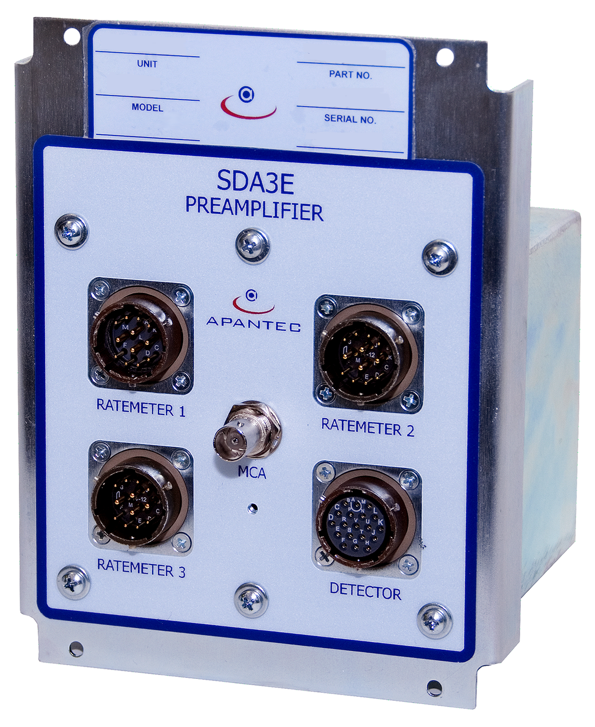
APANTEC also provides the model SD201PB Beta Scintillation detector for monitoring beta activity. The SD201PB is similar in construction and design to the SD200N, but replaces the gamma sensitive NaI crystal with a thin NE102 plastic scintillator. The detectors operate in conjunction with the SDA3E analyzer unit. The SDA3E takes the power from the ratemeter and provides low and high voltage power required for detector operation. The SDA3E unit also drives the LED in the detector and takes the signal from the temperature sensor. It then compares the LED signal from the PM tube with a temperature compensated reference signal and generates a correction voltage to automatically adjust the high voltage to provide gain stabilization.
| Sensor: | 2" x 2" NaI crystal |
| Detector Output: | Analog negative pulse |
| Detector Accuracy: | ±15% of true field intensity |
| Detector Linearity: | ±5% |
| Operating Temperature: | 14 to 122 °F (–10 to 60 °C) |
| Operating Voltage: | 450 to 1500 V |
| Nominal LED Background: | 10 to 15 CPM |
| Operating Humidity: | 0–95% non-condensing |
| Housing: | Moisture Proof Stainless Steel, 2.7 kg (5 lb) |
| Sensor: | Beta, NE102 plastic (2" dia. X 0.01" thick) |
| Detector Output: | Negative Pulse |
| Detector Accuracy: | ±15% of true field intensity |
| Detector Linearity: | ±5% |
| Operating Temperature: | 14 to 149 °F (–10 to 65 °C) |
| Operating Voltage: | 500 to 1500 V |
| Nominal LED Background: | 10–15 CPM |
| Operating Humidity: | 0–95% non-condensing |
| Housing: | Moisture Proof Stainless Steel, 2.7 kg (5 lb) |
| Input Impedance: | 9.1 K |
| Voltage Gain: | 16 |
| Output Signal: | Approx. 1 mV per keV |
| Operating Temperature: | 14 to 122 °F (–10 to 50 °C) |
| Energy Low Range: | 50 keV to 2.55 MeV |
| Energy High Range: | 1.5 MeV to 7.5 MeV |
| Housing: | NEMA-4X stainless steel box |
| Size: | 152.4 x 152.4 x 101.6 mm (6 x 6 x 4 in.), 2.2 kg (4 lb) |
| Power: | ±12 V |
| Placement from Detector: | Up to 5 m (15 ft) |
| Placement to Ratemeter: | Up to 293 m (~1,000 ft) |
| SCA Channels: | 3 |
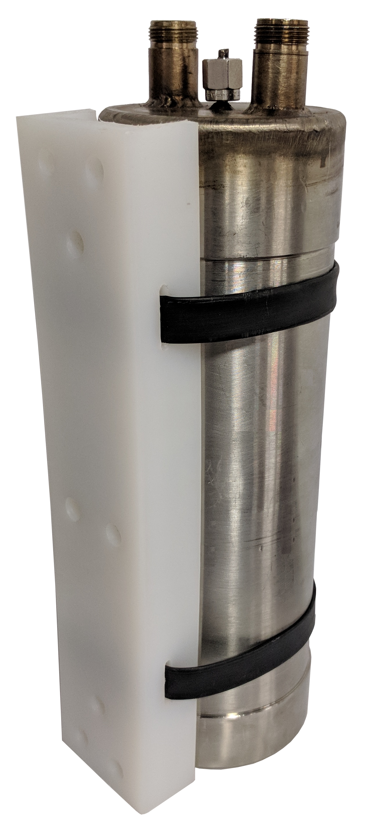
The CIC1H Ion Chamber detector is a sealed ion chamber probe packaged in a cylindrical stainless steel enclosure and fitted with two coaxial connectors for interconnection to an associated CIC1F Current-to-Frequency convert. The CIC1F converts the ion chamber output current into TTL level pulses suitable for counting by an APANTEC RM series display unit. The CIC1H is used on those channels with anticipated high activity such as containment / post accident detection. The detectors are qualified for operation in LOCA accident level conditions. The associated RM display and control unit provides Ethernet and serial RS485 communications for networking to a central computer using the APANTEC DORIS software. The CIC1H measures a range of 2.5E-1 to 5E+7 R/hr.
| Detector Type: | Ion chamber, sealed |
| Range: | 2.5E-1 to 5E+7 R/hr |
| Energy Response: | ±30% from 80 keV to 2.5 MeV (Referenced to 137Cs) |
| Accuracy: | ±40% over entire range |
| Operating Temperature: | 14 to 375°F (-10 to 191 °C) |
| Operating Humidity: | Up to 100% RH |
| Operating Voltage: | 1500 VDC maximum, supplied by CIC1F |
| Dimensions: | 13.6 in. L x 3 in. dia. |
| Weight: | 3 lb (1.35 kg) nominal |
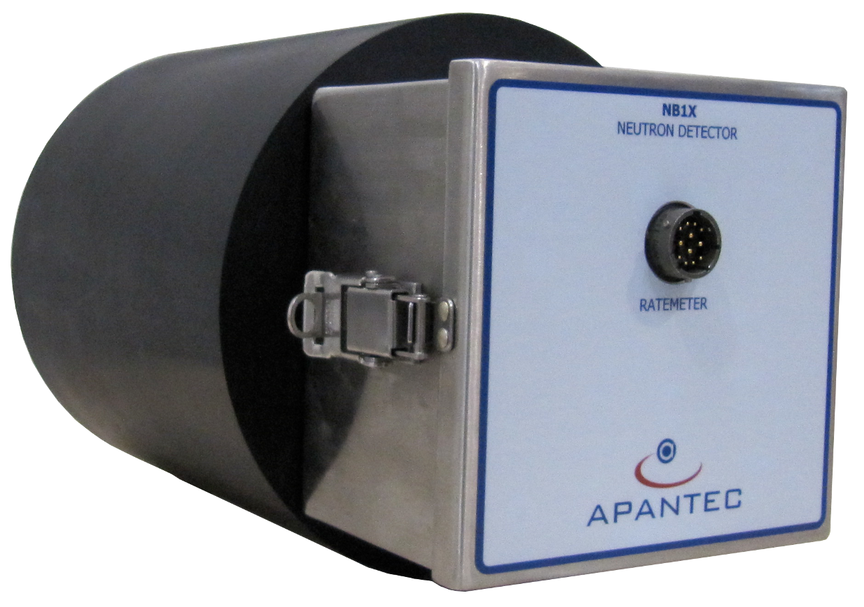
The APANTEC Neutron Probe is based on the design by I. O. Anderson and J. Braun and provides dose response corresponding to the human body. It measures directly the biological dose rate of neutrons in energy from thermal (0.025 eV) to 15 MeV. The Neutron Probe contains a proportional counter, which produces pulses resulting from neutron interactions occurring within it. The proportional counter is essentially a thermal neutron detector, but the probe is designed to respond to thermal, epithermal and fast neutrons. The probe includes a high hydrogen content polyethylene moderator, which moderates and attenuates neutrons so that the net incident flux at the proportional counter is a thermal and low epithermal flux representative of the tissue equivalent dose rate due the neutron field. In addition, the proportional counter is enclosed with a tissue equivalent boron impregnated sleeve, which provides the interaction between the neutrons and the counter. The NB1X/NH1X provides a pulse output to an associated RM series display unit for display and control. The RM series display unit provides serial RS485 and Ethernet communications for networking to a central computer using APANTEC's DORIS software. The NB1X/NH1X is available in the following configurations.
| Detector Type: | NB1X: BF3 counter with Boron impregnated sleeve and polyethylene moderator
NH1X: He-3 counter with Boron impregnated sleeve and polyethylene moderator |
| Range: | 0.1 μSv/h to 100 mSv/h |
| Energy Range: | 0.025 eV to 15 MeV |
| Energy Response: | ±20% from 0.025 keV to 15 MeV |
| Accuracy: | ±15% over entire range |
| Linearity: | ±5% |
| Response Time: | 4 s |
| Operating Temperature: | -31 to 140 °F (-35 to +60 °C) |
| Operating Humidity: | 0-95% RH |
| Operating Voltage: | +12 VDC, biasing voltage supplied by RM unit |
| Dimensions: | 12 in. (304.8 mm) L x 8 in. (203.2 mm) dia. |
| Weight: | 20 lb (9 kg) nominal |
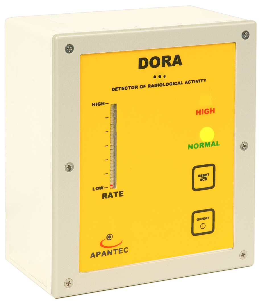
DORA is an integrated real-time Gamma radiation monitoring device that provides a highly accurate indication of ambient Gamma activity over a wide range. The DORA provides normal/high radiation indication locally and comprehensive rate, dose and status information to a remote computer system or display unit through a high speed Ethernet TCP/IP network. It is built around a high-speed microprocessor core that handles all measurement, indication, communication, and historical record retention. The microprocessor system integrates program FLASH memory for firmware storage, high speed SRAM for program execution, battery backed SRAM for short-term history storage, xD memory card for expanded long term history storage, real time clock (RTC), Ethernet interface, and serial communications ports for the RS485 and USB interfaces. The RS485 port provides an alternate interface to the Ethernet port for remote data access. The USB port is provided for configuration changes and firmware upgrades only.
The built-in halogen quenched GM tube, high-voltage supply, and time-to-count driver are the heart of the radiation measurement system. The 1" diameter by 2" long GM tube, with energy compensation shielding, provides a nominal sensitivity of 1700 CPM / mR/hr. The GM tube and time-to-count control techniques give an accurate and highly linear operation from 10 μR/hr background to 10 R/hr.
APANTEC also provides a version of DORA that has an extended range measurement using two GM sensors located within the DORA enclosure. This optional version will measure a dynamic range of 10 μR/hr to 10,000 R/hr. The energy compensation shield provides uniform energy response over 80 keV to 2.5 MeV. The high voltage power supply is generated internally to provide bias voltage for the GM tube. Energy response for H*(10) Seivert response is also available covering a range of 0.1uSv/hr to 100 Sv/hr.
Dose rate, integrated dose, and status information are available over TCP/IP Ethernet or RS-485 serial communications. An analog output is also available to provide indication of dose rate, programmable over the dynamic range as a 0-10 VDC signal.
Radiation trend is displayed with a trend bar. Two LED’s, an audible alarm, and a relay contact for an external indicator communicate status. The LED’s are green for Normal and red for High Alarm. The audible alarm can be muted while the alarm condition still exists by pressing the reset/ack button. The relay provides a contact closure on high alarm. The contacts are isolated from the rest of the probe’s circuitry and may be used to control an external annunciator.
The DORA is also adaptable to process radiation measurement with an integrated analog input. The analog input allows the unit to monitor external process variables such as temperature, flow or pressure.
The DORA in housed in a NEMA 12 enclosure for wall mounting. The enclosure allows the probe to be used in a variety of environments without impacting operation or accuracy. An external "smart" probe port allows expandability and detection of radiation in wide applications. A wide variety of external "smart" probes for measuring alpha, beta, gamma and neutrons are available.
| Detector: | Halogen quenched energy compensated GM tube |
| Sensitivity: | 1700 cpm/mR/h |
| Range: | 10 μR/hr to 10 R/hr. |
| Indicators: | Alarm: Red Normal: Green Audible:80 dB @ 3ft |
| Outputs: | Digital: (1) TCP/IP Ethernet, (1) RS-485 serial Analog: (1) 0-10VDC Alarm Relay: 150 mA @120 VAC, 150 mA @ 28VDC |
| Inputs: | 0-5 VDC analog input |
| Power: | 12 VDC, 0.5A nominal (9 VDC to 15 VDC), optional 110/220 VAC 50/60 Hz converter available |
| Operating Temperature: | -4 to 122 °F (-20 to 50 °C) |
| Operating Humidity: | 0-95% RH, non-condensing |
| Dimensions: | 5" high x 4" wide x 3" deep |
| Weight: | 2 lb (0.9 kg) |
Display and control of the radiation monitoring channels can be accomplished using either discreet RM series microprocessor based display and control units or using a DORIS central database software program. Each APANTEC instrument module includes an Ethernet interface, allowing each device to be interconnected using readily available CAT5 communications cable.
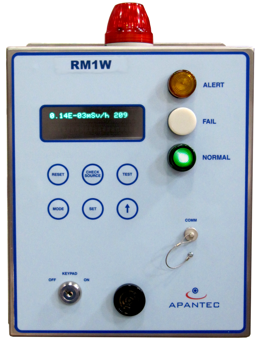
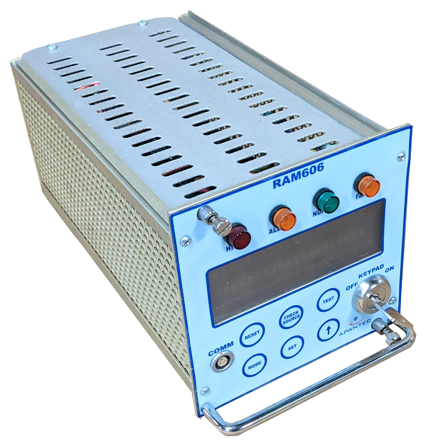
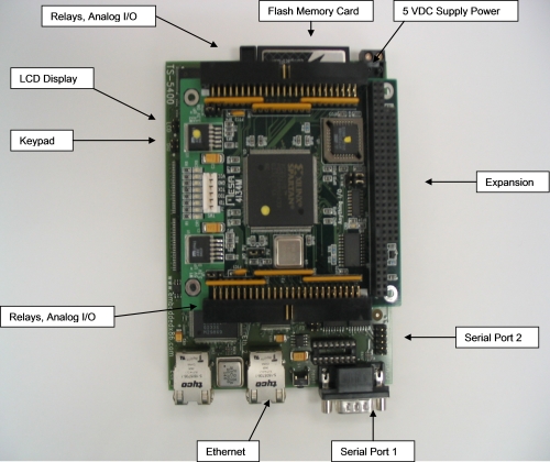
The RM Radiological Activity Monitor series instruments are used as distributed display and control units with multi-function capabilities. The units utilize a 32-bit ARM-based microcontroller that handles three timer/counter acquisition channels, user interface (display, keypad, indicators), analog I/O, digital I/O, robust communication capabilities such as RS-232 serial ports, RS485 serial ports, and or optional TCP/IP Ethernet communication for networking. Digital and analog Input/Output (I/O) circuitry is included to allow the RM units to operate as data concentrators and controllers for devices external to the RM unit. The RM design has three radiological counting channels, allowing simultaneous processing of radiological data from up to three "smart" sensor channels.

Information is displayed on a 2 line by 20 character vacuum fluorescent display mounted on the front panel of the RM unit. In addition to the main display, the RM also provides discreet indicators for instrument status, such as High, Alert radiation alarms, and Fail/Malfunction conditions. An audible sounder is also included for audible annunciation of a radiological alarm on RM1W wall-mounted units. The RM series instruments are provided in two packaging arrangements. The RM1W is provided in a NEMA12 wall-mount enclosure and is typically used as the local display and control device. The RM1R is provided in a chassis mounted configuration and is typically used as the remote control room display and control unit. Both units are functionally equivalent and use common circuit board designs. Operators interface with the RM unit using a keypad switch that is protected using a key lock switch and/or password. The keypad switch is located on the front panel and provides controls for setting and viewing alarms, establishing parameters for detector operation, alarm acknowledgement, check source operation, and administrative functions such as setting the channel identification information.
When used with process or effluent monitoring channels, the RM unit acts as a data concentrator and data processing unit, integrating external signals such as flow rate and pressure into the radiological measurement. Analog signals are integrated into the RM microprocessor circuit using analog-to-digital converters (ADC), which are 16 bit resolution devices. Five ADC circuits are included for external sensors. The RM also accepts up to six digital input signals for operation with external digital devices. This feature is often used for such applications as normal and accident range noble gas monitoring, where a digital signal is used for automatic switchover between the normal range and accident range monitoring systems. Outputs from the RM include three RS485 serial communications ports (or optionally up to 2 Ethernet ports (Modbus over TCP/IP) , one RS232 communications port, four 4-20 mADC or 0-10 VDC analog outputs, eight digital output circuits and five DPDT (2 form C) relays and one SPDT (1 form C) relay. The relays are factory programmable to provide customized configuration. Typically this will include a relay for high radiation alarm, warning radiation alarm, fail conditions, check source activation, and miscellaneous alarm circuits such as low flow conditions. The analog outputs are scaled to the dynamic range of the measurement channel and are provided via a 16-bit resolution DAC device. The analog output signals are optically isolated.
The RS485 serial communications ports and Ethernet TPC/IP port are provided for networking the RM units with database software or other remote display and control units. The RS232 port is provided on the front panel for ease of access and software configuration with portable devices. The RM series units operate from 24 VDC, which is supplied using an AC to DC converter. The converter accepts universal AC input power ranging from 90 VAC to 260 VAC, 47 Hz to 63 Hz, single-phase power. The power supply is UL and CE certified and is filtered to prevent disruptions due to dropouts, voltage variations, surges and spiking. Critical operating parameters are stored in non-volatile EEPROM memory to ensure that the system quickly recovers from power outages without operator intervention. Historical data is retained in battery-backed non-volatile memory for up to 100 hours after loss of primary power. Operating parameters are field configurable allowing customer personnel to use a common design platform for multi-function channel and display configurations.
The RM series ratemeters are qualified for seismic, EMI/RFI and environmental conditions per the latest Nuclear Industry Standards.
| Processor: | 32-Bit High Performance ARM-base Integrated Microcontroller, with three integrated timer/counter channels for data acquisition, four UARTs for serial communications, digital I/O for user interfaces, watchdog timer, battery-backed RAM, program FLASH memory, and real time clock. |
| Display: | 2 x 20 character vacuum fluorescent display |
| Alarm/Status Indicators: | Red indicator: HIGH Amber indicator: ALERT White indicator: FAIL Green indicator: NORMAL Audible alarm (RM1W only) |
| Outputs: | Digital: (1) RS232, (3) RS485, or optionally (2) Ethernet Analog: (4) 0-10VDC, or (4) 4-20 mADC isolated Relays: (6) DPDT and (1) SPDT relays for FAIL, ALERT, HIGH & other alarms (Relay contact rating 5A @ 115VAC resistive) |
| Power: | 90-260VAC, single phase, 47 to 63 Hz, 15 watts |
| Operating Temperature: | 14 to 122 °F (-10 to 50 °C) |
| Operating Humidity: | 0-95% RH, non-condensing |
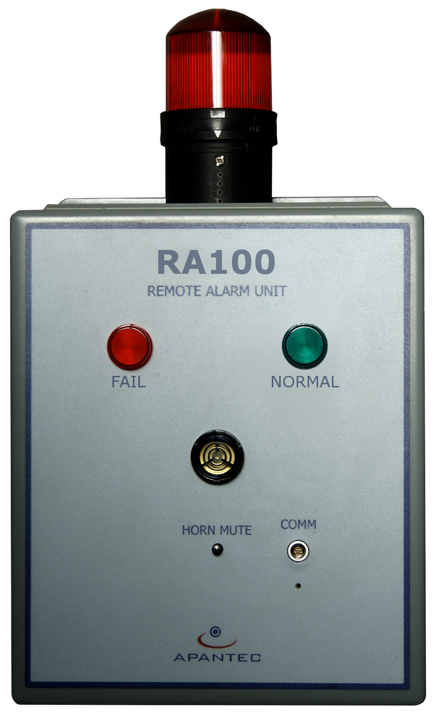
The RA100 is used for remote annunciation of alarm status from an associated RM1 display and control unit. It is often desirable to provide an alarm indication at a location other than the display and control device to protect personnel from increased radiation activity levels. The RA100 includes indicators for High radiation, Alert radiation and Fail conditions. A red indicator is illuminated should the measured activity level exceed the established High alarm setpoint. A yellow indicator is illuminated should the measured activity level exceed the established Alert alarm setpoint. A white indicator is illuminated should the measurement channel malfunction in some fashion. An audible alarm is also provided for annunciation of a High radiation alarm condition. The RA100 includes an Ethernet interface for interconnection with an associated RM1 display and control unit or DORIS database software. The RA100 is provided in a NEMA4 rated wall mounted enclosure and will operate in an environment of 0C to 60C and a humidity of 0-98%RH (non-condensing).
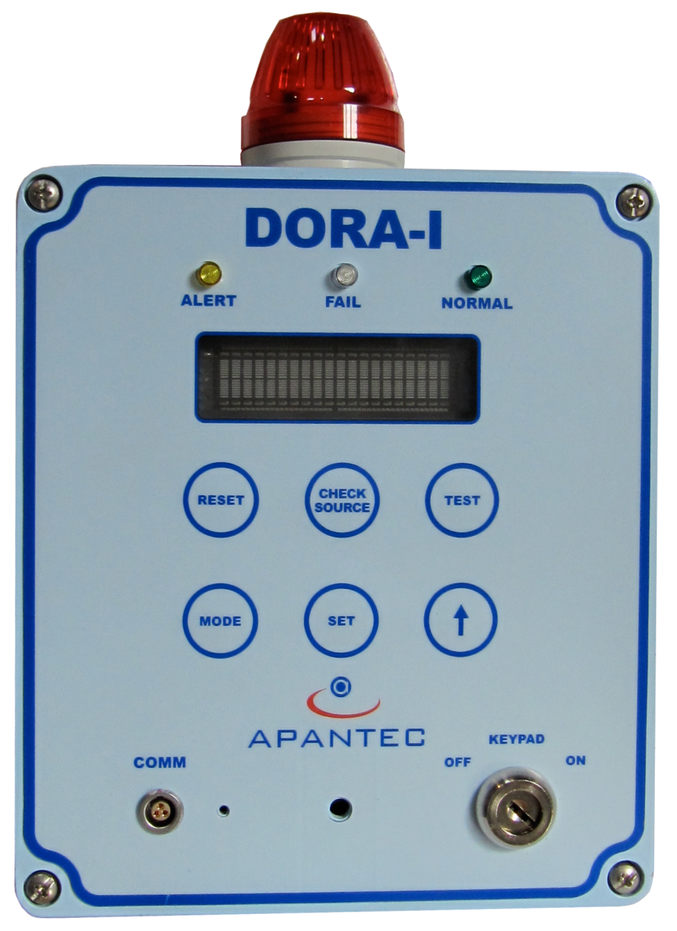
The DORA-I Series Radiological Activity Module is a single board low power ARM processor controlled digital ratemeter, designed to power, operate, and monitor various types of APANTEC, LLC smart radiation detectors. The DORA-I unit is a wall mounted unit that can be mounted to any vertical surface.
The DORA-I SERIES is equipped with a connection which provides isolated relay closures, isolated 4-20 mA current loop output, isolated RS-232/485 serial communications, and 10/100Base-T Ethernet.
The DORA-I SERIES ratemeter can operate with APANTEC Area Monitor type detectors and Process Monitor type preamplifiers and detectors. It can also be equipped with an internal G-M detector and optional checksource. With either detector type, the ratemeter provides all detector power and control signals required for operation. The Area Monitor type detectors consist of detectors designed for area detection of gamma or neutron radiation. The Process Monitor type detectors consist of detectors designed to be mounted in fluid or gas flow streams such as liquid piping systems, ventilation ducts and stacks.
The DORA-I series units operate from 30-70 VDC Power-Over-Ethernet or +24 VDC, which is supplied using an AC to DC converter. The converter accepts universal AC input power ranging from 90 VAC to 260 VAC, 47 Hz to 63 Hz, single-phase power. The power supply is UL and CE certified and is filtered to prevent disruptions due to dropouts, voltage variations, surges and spiking. Critical operating parameters are stored in non-Volatile EEPROM memory to ensure that the system quickly recovers from power outages without operator intervention. Historical data is retained in non-volatile memory Operating parameters are field configurable allowing customer personnel to use a common design platform for multi-function channel and display configurations.
| Housing: | NEMA 12 (JP 56) wall mount |
| Weight: | 8 lb (3.6 kg) |
| Operating Temperature: | 14 to 122 °F (-10 to 50 °C) |
| Operating Humidity: | 0-95% RH, non-condensing |
| Input Power: | Power-Over-Ethernet, 30-70 VDC, (optional) 24VDC. |
| Maximum Input Current: | 0.50 A |
| Detector Interface: | Provides power, control and counting for two detector channels, one internal and one external. Compatible with APANTEC, LLC. smart detectors |
| Internal Detector: | GM Tube with checksource (optional) |
| External Detector: | As required. Compatible with neutron detector, GM detector, or ion chamber detector |
| User Interface: | Keypad: six position keypad Key Switch: three position to provide unit ON, OFF and KEYPAD mode lock out feature Display: vacuum fluorescent alphanumeric, two rows of 20 characters |
| Processor | NXP LPC2388 ARM-7 microcontroller designed for real-time applications. |
| Alarm Indicators | Red indicator: HIGH Amber indicator: ALERT White indicator: FAIL Green indicator: NORMAL |
| Outputs: | Digital (1) RS232/485 and (2) TCP/IP Ethernet Analog (1) 0-10VDC, or (1) 4-20 mADC isolated Two DPDT relays for FAIL, ALERT, HIGH and other alarms or controls, programmed as required |
| Communications: | MODBUS |
| Displays: | Dose rate Alert and high alarms Power-on indicator |
| Keypad Accesses: | Measurement range selection Set point adjustment Input power supply selection Stored data access Local reset of warn/high alarms |
| Security | Key switch |
| Remote Controls: | Alarm setpoints Reading radiation data Write alarm acknowledge Forced alarm activation Read internal diagnostic features Alarm trip times |
| Audio and Visual Displays: | Flashing or steady, as desired Programmable duty cycle for flashing |
The LS44 liquid sampler is provided for offline monitoring of liquid samples. The sampler is shielded with up to four inches of lead arranged in a 4Pi configuration.
A drywell located within the detector shield provides a repeatable geometry for the scintillation detector as well as providing a pressure boundary. The sample chamber is arranged with a self-cleaning action to reduce the build up of crud and contamination. The sample chamber liner is easily decontaminated if needed to allow the monitoring system to maintain the original sensitivity. An external riser pipe and self-venting sample chamber ensure that there are no voids in the sample volume for accurate determination of liquid concentrations.
The sampler bowl is constructed of highly polished stainless steel, with wetted surfaces fabricated of corrosion resistant stainless steel. The LS44 sampler will operate in liquid pressures up to 150 PSIG. Standard process connections to the sampler are performed via 150 RF flanges with NPT connections optionally available.
| Sampler Volume: | 5.8 liters |
| Lead Thickness: | 4 inches |
| Max. Pressure: | 150 psig, hydrostatic tested to 225 psig. |
| Weight: | ~1,450 lb (~658 kg) |
| Exterior: | painted cold rolled steel |
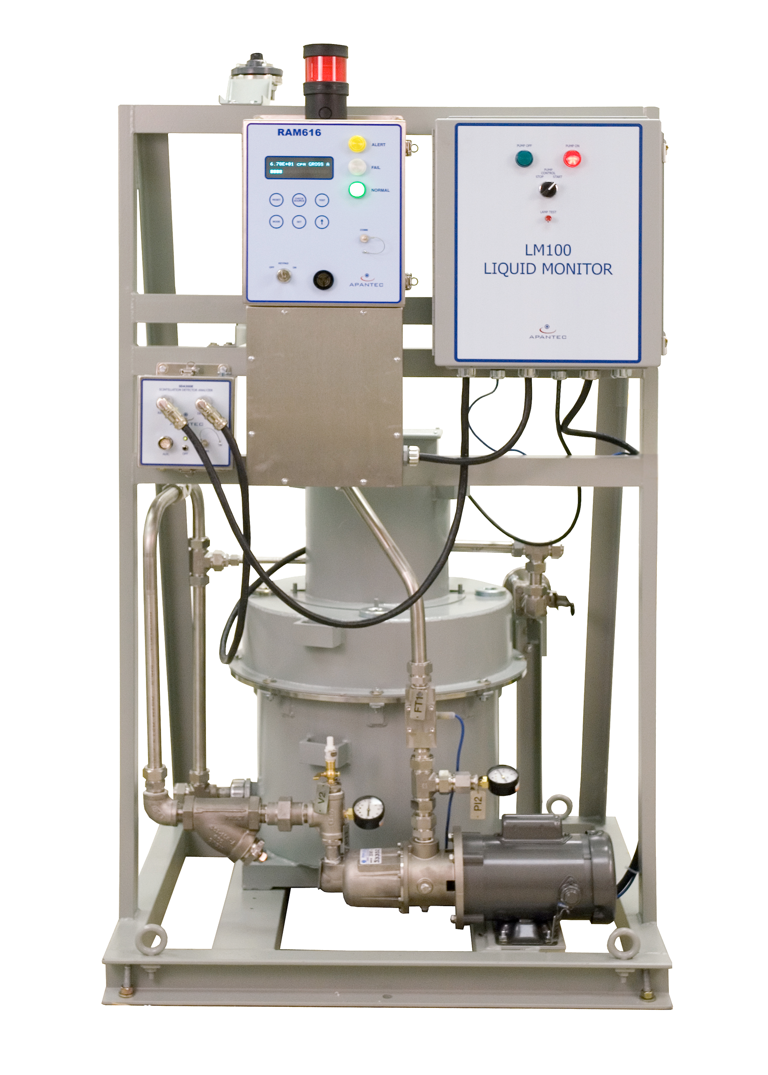
The liquid monitoring system is provided on a single open frame skid suitable for mounting to a floor location. Lifting rings and forklift access are provided for movement of the system to the monitoring location. The system also includes a liquid pumping system capable of generating in excess of 20 GPM flow through the system with a head lift of in excess of sixteen feet. The liquid pump is a centrifugal type pump close coupled to a ¾ HP electric motor. A basket strainer upstream of the pump suction removes large entrained materials from the liquid sample to provide protection to the pump. Local ON/OFF pump controls are provided on the system skid. Remote pump operations are optionally available. A flow indicator and flow control valve are included for establishing the desired flow rate through the monitoring system. Fittings and valves for purging the liquid sampler are also available.
The IS4X Fluid Sampler is an in-line shielded unit providing four inches of lead shielding around the pipe to be monitored, and the detector. A drywell inside the sampler provides a repeatable geometry for measurement. The IS4X series sampler model number is based upon the pipe size that is being monitored. The IS4 sampler is designed for pipe sizes from two inches and higher in diameter. When used on pipe sizes four inches or smaller, the IS4X sampler expands the sample volume to provide a minimum of five liters of sensitive volume.
The OS4A Online Sampler is an adjacent-to-line shielded unit providing four inches of lead shielding around the pipe to be monitored and the detector. A drywell inside the sampler provides the detector with a repeatable geometry for measurement. The OS4A series sampler is a split shield design that bolts to the exterior of the pipe that is being monitored. The OS4A sampler is for pipe sizes four inches and higher in diameter.
| Sampler: | 150 lb rated pressure |
| Shielding: | 4" lead in a 3Pi geometry |
| Flow Rate: | Determined by existing flow rate |
| Sampler Weight: | 600 lb nominal |
| Process Fluid Temperature: | 30 to 130 °F (-1.11 to 54.4 °C) high temperature systems available |
The AS43F sampler is provided for monitoring of particulate and/or iodine activity. The sampler is shielded with up to three inches of lead arranged in a 4Pi configuration. A detector mount located within the shield provides a repeatable geometry for the scintillation detector as well as providing a pressure boundary. The AS43F sampler is an easy to use design that uses a fixed filter holder for collection of airborne radioactive particles and/or iodines. The filter holder accepts industry standard 47 mm diameter filter paper as well as provisions for use of a TEDA or silver zeolite cartridge for capture of iodines. When used for particulate monitoring only, the cartridge is replaced by a backing screen to provide support for the filter paper.
The scintillation detector, when installed within the sampler, is in close proximity to the deposited material for maximum sensitivity. The sampler is constructed of painted cold rolled steel with corrosion resistant stainless steel used on wetted surfaces.
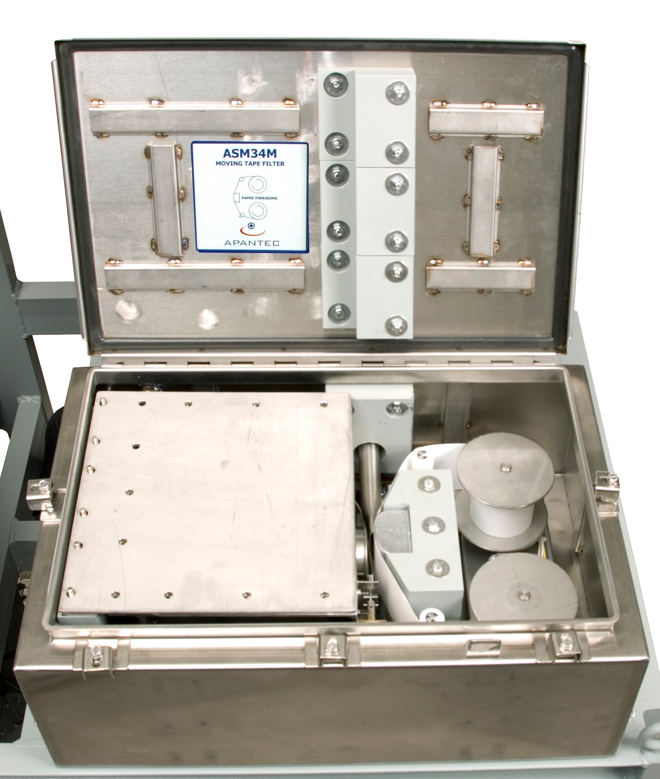
The AS34M sampler is provided for monitoring of particulate and/or iodine activity. The sampler is shielded with up to three inches of lead for attenuation of gamma background activity. A detector mount located within the shield provides a repeatable geometry for the scintillation detector as well as providing a pressure boundary. The AS34M sampler is an easy to use design that uses a moving filter sampler for collection of airborne radioactive particles and/or iodines. The sampler accepts filter media in a roll form that can be either standard filter media for collection of particulate activity or charcoal impregnated media for collection of both particulate and iodine activity. The sampler is designed so that the scintillation detector, when installed within the sampler, is in close proximity to the deposited material for maximum sensitivity. The sampler is constructed of corrosion resistant stainless steel used on wetted surfaces. Standard process connections to the sampler are performed via 1" NPT connections.
| Filter Paper: | Particulate: roll 3" wide equivalent to H&V LB5211 |
| Iodine: | TEDA impregnated Type 72 99% retention of 0.3 micron or larger particles & iodine at 1 SCFM/30 LPM |
| Vacuum Pump: | Progressive cavity carbon vane, diaphragm, or Metal Bellows 5 in/hg at 1 SCFM flow1 |
| Flow Rate: | 0-1 SCFM (0-30 LPM) rotameter standard, optional thermal mass flow measurement (Accuracy ±15%) |
| Flow Totalizer: | Continuous totalization until reset |
| Power: | 220 VAC, 50/60 Hz, single phase, or 120 VAC, 50/60 Hz, single phase |
| Outputs: | Low Flow Alarms, DPDT Relay, 5A, 120 VAC rated Visual Display on RM1W digital display |

The APANTEC GS45 Noble Gas Sampler is provided for continuous monitoring of noble gas activity. The sampler is shielded with four inches of lead arranged in a 4Pi configuration. A well located within the detector shield provides a repeatable geometry for the scintillation detector and exposes the sensitive element of the detector to the gaseous activity. The sample volume provides sufficient gas volume to meet required sensitivity with a nominal volume of 5 liters. The sample conditions are automatically corrected to standard pressure using a vacuum transducer located at the sampler volume inlet. The sampler is constructed of steel with wetted surfaces fabricated of corrosion resistant stainless steel. The GS45 Noble Gas Sampler is designed for operation under vacuum conditions up to 5 psig. Process connections to the sampler are performed via dual ferrule compression fittings on 300 series stainless steel seamless tubing.
The air monitoring system is provided on a single open frame skid suitable for mounting to a floor location. Lifting rings and forklift access are provided for movement of the system to the monitoring location. The system includes a vacuum pumping system capable of generating in excess of 1 SCFM flow. The pump is a carbon vane progressive cavity or metal bellows pump with integral fractional horsepower motor. Local ON/OFF pump controls are provided on the system skid. Remote pump operations are optionally available. A flow indicator and flow control valve provide desired flow rate through the monitoring system.
| Filter Paper: | Particulate: 47mm to 57mm Iodine: TEDA impregnated Type 72 2.25 in. dia (57.1 mm dia) 99% retention of 0.3 micron or larger particles and iodine at 1 SCFM (30 LPM) |
| Vacuum Pump: | Progressive cavity carbon vane, diaphragm, or Metal Bellows5 in/hg at 1 SCFM flow |
| Flow Rate: | 0-1 SCFM (0-30 LPM) rotameter standard, optional thermal mass flow measurement (Accuracy ±15%) |
| Flow Totalizer: | Continuous totalization until reset |
| Power: | 220 VAC, 50/60 Hz, single phase, or 120 VAC, 50/60 Hz, single phase |
| Outputs: | LOW FLOW Alarms, DPDT Relay, 5A, 120 VAC rated Visual Display on RM1W digital display |

APANTEC offers a comprehensive software "tracking and trending" program called
APANTEC offers a full service preventive maintenance, repair, and refurbishment programs to support Nuclear Generating Stations which are currently using both Nuclear Research Corporations and Canberra supplied detectors, preamplifiers as well as remote and local alarm indicators.
APANTEC has dedicated repair and test facilities as part of the manufacturing and test departments to accommodate the fabrication, repair, and testing of all equipment. In addition, APANTEC offers free phone support for troubleshooting questions.
Our factory services include a full range of options including equipment repair, calibration, preventive maintenance and parts ordering. All equipment is serviced by a staff of highly skilled technicians using automatic test equipment and test instruments calibrated to NBS traceable standards. Calibrations certificates to comply with your quality program requirements are available upon request.
APANTEC, LLC proposes to repair and calibrate the Nuclear Research Corporation/Canberra Industries electronics instruments to factory condition. ALL instruments will be returned with a one year factory required.
APANTEC can provide a one time engineering service to determine the configuration of all Nuclear Research Corporation (NRC) and Canberra Industries (CI) provided radiation monitoring system spare parts. As part of this service, APANTEC includes a one-day on site evaluation of equipment and documentation. At the completion of the engineering study, APANTEC will provide a comprehensive list of all recommended spare parts, complete with document control numbers and configuration information for each channel. APANTEC will also provide recommendations for the quantity and type of spare parts to be maintained both on site as ready/critical spare parts and at APANTEC for off site support and hot stand by.
APANTEC is committed to quality service following the delivery and installation of the instruments. APANTEC offers full logistics support during the life of our equipment, and complete customer service including engineering, startup and training services.
APANTEC offers several upgrade paths for existing customers who are presently using Nuclear Research Corporation (NRC) or Canberra radiation monitoring system instruments. Instruments can be refurbished to factory conditions, upgraded by replacing the electronics with latest generation designs, or complete form, fit and function replacements. This methodology extends the service life of the original equipment by providing a readily available source of spare parts, replacement modules and service.